How is a load cell made?
The construction phases: machining the steel workpiece, assembling the mechanism, packing and shipping.

How is the compression load cell CBL 250-12500 created?
From machining the steel workpiece to packaging and shipping, through gluing the strain gauges, wiring, calibration and testing...here are all the steps in the construction process that turns a simple steel cylinder into the most important component of a weighing system.
1. Cutting, turning and milling
The construction of the load cell starts in the mechanical workshop where the 17-4 PH stainless steel bars arrive to be transformed.
17-4 PH stainless steel, due to its elasticity and hardness, is a particularly suitable material for load cells.
When combined with the proper strain gauges, it has a very small error on the hysteresis cycle.
This characteristic allows it to remain flexible even for very high forces: it deforms under a load and then returns to its initial condition when the load is no longer acting.
All bars are certified with an ultrasonic machine to rule out any imperfections in the steel. Then each bar is marked with its diameter and casting number so that the batch is easily traceable.
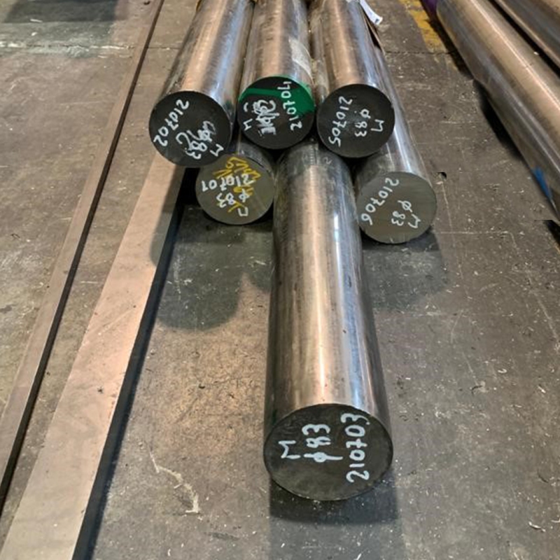
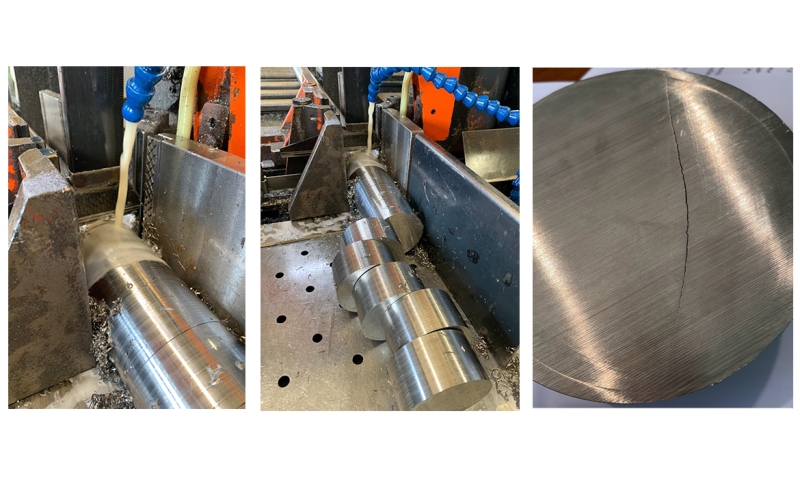
The bar is cut into cylinders, which are then checked one by one to make sure that there are no "cracks".
Cracks are often hairline cracks invisible to the human eye and may cause future problems when manufacturing the load cell or operating it.
Once the checks are passed, the cylinder is machined in 3 stages: two on the lathe and one on the milling machine.
- During the first stage of turning, the operator makes the slot in the load cell, in which the strain gauges will then be placed.
- In the second stage of turning, the upper loading button, typical of CBL load cells, is made on the opposite side of the cylinder.
- In the third stage, the socket for the cable gland and the hole for the cable to pass through are also made with a milling machine.
The load cell mechanics are ready for moving on to the next stage of manufacture.

During the 3 steps of manufacture, the cylinder loses most of its original material which becomes "wastage" (scrap) and its weight decreases from 2 kg to 650 g.
2. First mechanical checks and washing
Once the blank body of the load cell has been received by the workshop, the first mechanical test is carried out.
The operator, using a periodically certified gauge, checks that the dimensions are within the tolerances specified on the design drawing.
To remove all traces of impurities, the part is then washed a first time with a degreasing emulsion at a temperature of 50° for 40 minutes.
This is only the first wash the load cell will undergo, as a matter of fact it will be cleaned at least another 4 times.
Finally, all the clean parts are dried by hand one by one.

3. Heat treatments
The heat treatment of aging serves to eliminate and ease the tensions in the material and to bring the load cell to the desired hardness, improving its elasticity.
Aging leads to the core of load cell production.
The load cells are put in batches into the furnace while the management control panel oversees the operation and produces a graph and a certificate on the heat treatment carried out.
There are two types of industrial furnaces used for this treatment: air furnaces and muffle furnaces.
The air furnace acts by ventilation, while the muffle furnace uses spiral heating elements to produce heat.

For special load cells (such as those certified OIML R 60) the heat treatment involves a further step before aging: resolubilization.
During resolubilization, the load cell is treated at 1050°C in a high vacuum industrial furnace and then cooled to -80°C in a cryogenic oven.
The high vacuum furnace ensures that the load cell does not deform, while the thermal shock in the cryogenic oven eliminates tensions in the 17-4 PH stainless stell so that the load cell will be even more accurate and linear.
This stage of pre-aging is carried out on the blank piece before machining and eliminates all the tensions in the load cell.
4. Polishing and sandblasting
After heat treatment, the load cell is polished and sandblasted.
Polishing
The surface is brushed with an abrasive paste and made shiny to lower the roughness of the load cell and prevent material build-up, making it also easy to clean.
Sandblasting
With the aid of a sandblasting machine, the operator sprays glass microspheres onto the surface of the load cell making it porous.

CBL 250-12500 are polished on the outside and sandblasted only on the inside, so the strain gauges will adhere better to the body of the load cell due the porosity given to its surface by the sandblasting process.
The load cell is lastly washed again at 50°C and completely cleaned of sandy remains of the microspheres and greasy remains of the abrasive paste.
When the washing is completed, the load cells are stacked, being careful to insert a silicone disc between them. This will prevent them from getting damaged or scratched later on in the production cycle.
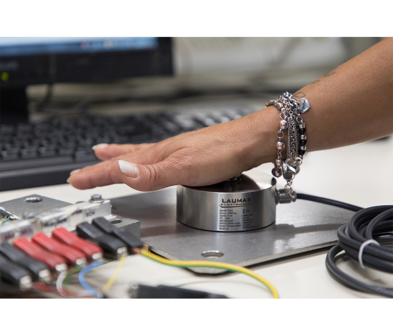
5. Dimensional and flatness check
The load cell is transported to the laboratory, where it is subjected to two checks: the dimensional and flatness checks.
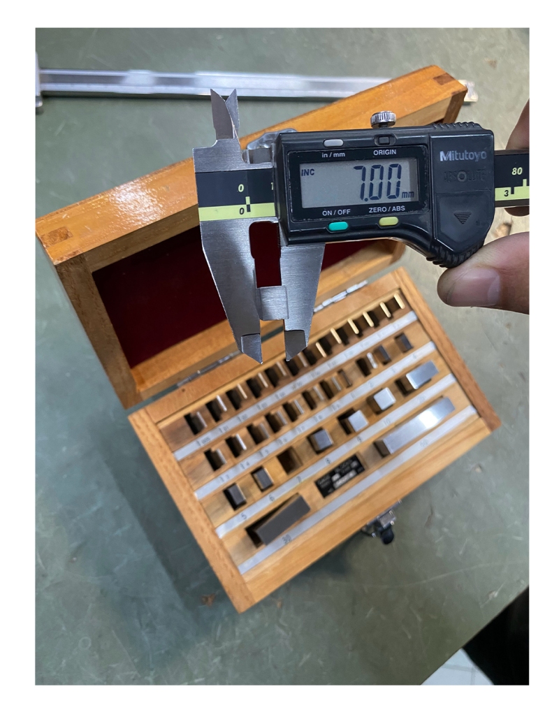
Dimensional check
The dimensional check is performed with gauges, which in their turn are calibrated with Johansson blocks.
What are Johansson blocks?
Also referred to as "flat parallel gauge blocks", they are magnetic steel parallelepipeds of varying thickness (0.01 to 10 mm) machined to obtain 2 perfectly parallel faces.
By rubbing and attaching together multiple blocks of different nominal value, the gauges used to measure the thickness of the load cell diaphragms can be verified.
Johansson blocks have an expiration time. They are therefore to be periodically reviewed to obtain a new certification, or replaced with new blocks.
Flatness check
To check the flatness, the load cell is placed on a perfectly flat surface and a force is exerted on it with your fingers.
If the load cell moves, the support crown is not perfectly flat and the load cell will be discarded. It is essential for it to remain still, otherwise it will not be able to work properly.

Is it Johansson or Johnson?
The most correct term is "Johansson blocks", named after Carl Edvard Johansson who created his first set in 1897.
Over time, however, "Johnson blocks" also became commonplace.
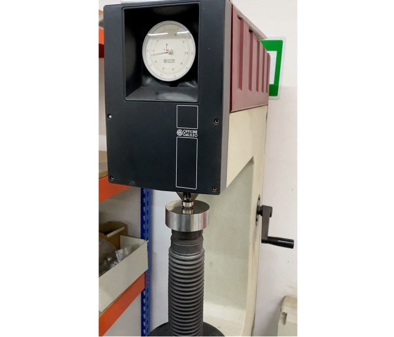
6. Hardness test
After polishing and the mechanical checks, the hardness of the load cell is checked.
Approximately 10% of the pieces are checked at random, which is sufficient to ensure that the whole batch meets the required parameters.
For this test, the operator uses a durometer, that is a machine with a penetrator that measures the degree of hardness taken on by the metal after the aging heat treatment, and confirms that the measured parameter is correct.
Different methods and scales can be used to perform the check. The most appropriate one is chosen depending on the shape and material of the penetrator and the preload and load forces applied.
In this case the chosen scale is HRC (Hardness Rockwell Cone), which is the one used for hardened steel parts.
The load cell is now ready for axis tracing and marking.
7. Laser tracing and marking
Both tracing and marking are done with a laser marker that can engrave any material, for an extremely clean and precise result.
Tracing
The tracing phase is critical. It is precisely here that, following the instructions on the drawing provided by the mechanical designer, the axes are engraved inside the load cell slot which during the gluing phase will show the operator where to position the strain gauges precisely.
Marking
The marker moves from one load cell to another and on each one engraves the specific label with the nameplate data to ensure full traceability.

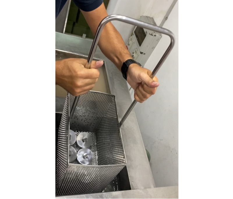
8. Ultrasonic cleaning
Once all the mechanical checks have been completed, the load cell is washed again.
This time an industrial ultrasonic washing machine is used to make sure it gets completely degreased.
The operator places approximately 10 kg of load cells into a basket and lowers it into the water at a temperature of 70°C. Here the load cells are subjected to a series of ultrasounds at 70Hz for 2-5 minutes and then rinsed.
After washing, the differce between polishing and sandblasting is clear and noticeable.
The surface of the polished load cell is smooth and causes the water to run off immediately; the surface of the sandblasted load cell is porous and retains the water, which takes longer to evaporate.
And if you only need to wash one load cell?
In this case, a fully BIO system is used which allows the water to be recycled. How? Once a month, a tablet containing micro-organisms that can "digest" the grease released from the load cell and keep the water clean is put into the system.
9. What is a strain gauge and how does it work?
The strain gauge is a small grid consisting of constantan wires (a binary alloy of copper and nickel) and is the sensitive measuring component of the load cell.
Glued inside the load cell slot, it follows the deformation of its surface.
When deformed, it causes a change in resistance, and therefore in electrical signal, proportional to the force applied to the load cell.
These variations are measured by making a Wheatstone bridge circuit.
The bridge connects multiple strain gauges to each other with electrical wires and a printed circuit board (PCB), which together detect the magnitude of deformation as a change in electrical signal expressed in mV/V (millivolts per volt).
10. Cleaning with conditioner and neutralizer
The load cell now reaches the most delicate department. It is here where the strain gauges are selected, positioned and glued expertly by skilled and specialized technicians.
Everything in this department is kept under the utmost control: the temperature is always between 20°C and 24°C, the level of humidity is kept constant and there is no dust whatsoever.
Everything is carefully monitored, nothing must affect the strain gauge and its isolation.
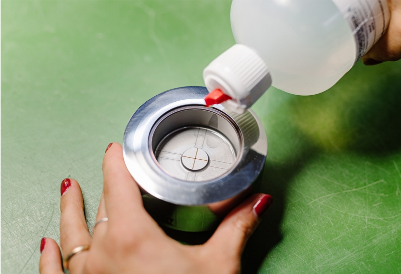
However, the load cell must be cleaned once again before gluing.
The technician cleans it by hand with two products: the conditioner and the neutralizer.
Conditioner
The conditioner is a compound of phosphoric acid which slightly corrodes the surface of the load cell and allows it to be completely degreased.
The technician pours a drop of conditioner into the slot to clean it thoroughly , then dries the residues with gauze.
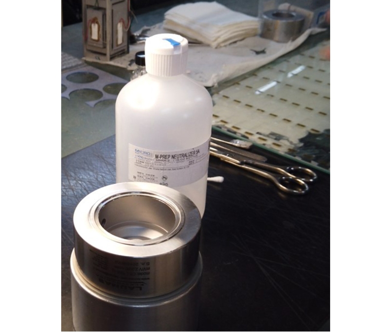
Neutralizer
The neutralizer is used to block the chemical reaction initiated by the conditioner and to create the optimum conditions of cleanliness for gluing the strain gauges.
It is applied after the conditioner and helps to ensure that the load cell is perfectly clean: if the conditioner has been effective, the drop of neutralizer will immediately expand on the surface of the slot.
The technician can now proceed with gluing.
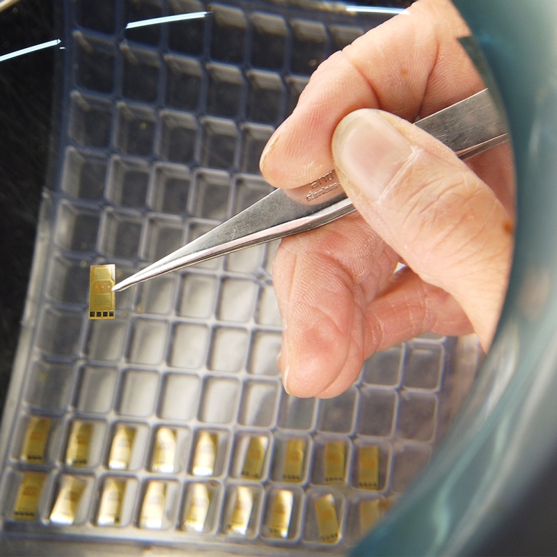
11. Gluing strain gauges
This is the most important step in load cell production.
It is precisely the accuracy of the gluing, performed by hand by extremely skilled operators, that esures optimum load cell perfomance in terms of repeatability, linearity and combined error.
Firstly, the operator takes the strain gauges from the package, places them in a row on a piece of glass and places the high-temperature resistant Mylar adhesive tape on top of it.
Then he brushes them with the glue on one side, the applies the glue also to the inside of the slot at the point already marked with the laser marker.
He now waits 4-5 minutes for the solvents in the glue to evaporate completely, so that the strain gauge will adhere perfectly to the load cell body.
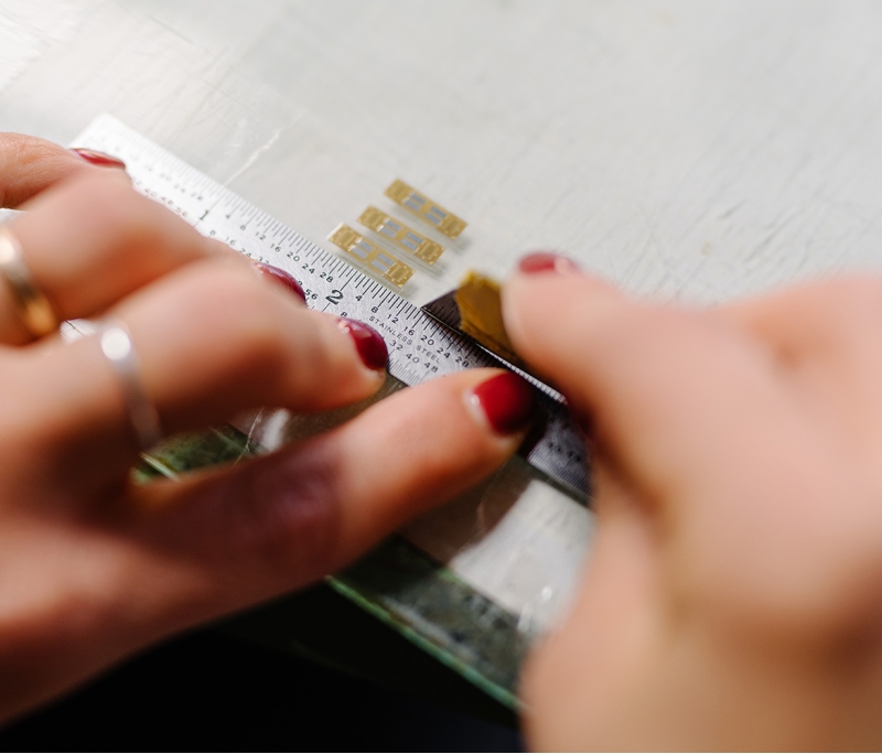
Finally, he accurately lays the strain gauges on the load cell and as a reference follows both the small arrows on the sides of their grid and the marks of the strain gauge drawing.
After gluing them, he protects them with a layer of Mylar tape on which he places the following in sequence:
- a Teflon disc
- a rubber disc
- a press-on Bakelite cap

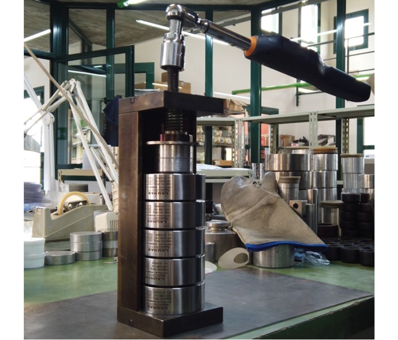
He groups the load cells together in a special pressure container and, with a torque wrench, tightens the screw on the head to the correct torque value.
This allows him top know and control the applied tightening force, avoiding damaging the strain gauges and changing the 0 of the load cell.
The block of load cells is baked at 175°C.
In this way, the glue will evaporate and the pressure exerted by the container will allow the load cell and strain gauge to become a single, indissoluble body,
12. Wiring
After gluing the strain gauges, the load cell wiring is made.
First, the operator removes the guards and Mylar tape from the strain gauges and checks thet they have fully adhered to the body of the load cell.
He then adds spots of tin on the pads of the strain gauges to connect the electric wires and proceed with wiring.
For each spot of tin he connects a wire and cleans the strain gauge to remove any residues left by the tinning.
This is done for all 4 strain gauges.

The upper part of the strain gauge is normally encapsulated, so that it does not risk getting damaged if a few drops of tin get dropped.
There are also non-encapsulated strain gauges that require more attention.
The operator can now connect the wires to the PCB specifically designed for the CBL load cell and create the Wheatstone bridge.
Having made the connections, he inserts a 6-core electrical cable into the load cell and places a small piece of heat shrink sheath between the mechanical body and the cable shield to prevent it from coming into contact with the load cell itself.
The 6-core cable works in pair:
- white and green for the signal branch;
- red and black form the power supply branch;
- ligh blue and yellow form the sense (or reference) branch that tells the instrument the actual power supply value that reaches the load cell.

The shield, or screen, is the protection around the wires of the electric cable and it is important ot be careful to connect it to the electronic instrument.
It is intended to protect conductors from any possible electromagnetic interference from the external environment and must never come into contact with the load cell.
For the last step, he places resistors in parallel to compensate for small changes in elastic modulus due to changes in temperature.
Once the wiring is complete, he carries out the last checks.
13. Calibration
The calibration test is used to measure the load cell response at 10 points up and 10 points down and the measured values are expressed in mV/V.
The response of a load cell must be directly proportional, i.e. linear, to the applied load (from 0 to its maximum capacity).

The electromechanical machine (which in other cases can be a hydraulic or direct load machine) applies a force corresponding to its maximum capacity to the load cell and compares it with a certified sample load cell, called the "primary load cell".
The capacity (or full scale) is the maximum weight the load cell can bear.
For example: for a load cell with a maximum capacity of 2500 kg, a load of 2500 kg is applied at the time of calibration.
At the end of the test, the machine returns a report indicating the resistance values to the operator to balance the zero and calibrate the rated output of the load cell.
Zero balancing
Zero balancing (or "load cell zero") is the value that the load cell returns when no force is exerted on it, i.e. it has no load on it.
To do this, the operator places the resistors in parallel on the PCB to allow balancing the Wheatstone bridge.
Rated output calibration
The rated output, expressed in mV/V, is the value that the load cell returns when the maximum load is applied, divided by the power supply voltage.
The rated output is also calibrated using resistors. Depending on the value resulting from the calibration test, the operator adds the resistors needed to correct the load cell until the correct output value (2mV/V±0.0200) is reached.
14. Temperature test
The load cell is placed in a climatic chamber, where the temperature test for the 0 thermal drift compensation takes place.
Each thermal test cycle lasts approximately 6/8 hours and is done by measuring the zero point of the load cell at a temperature of +20°C, -10°C, +50°C and finally again at +20°C.
Using an algorithm, the climatic chamber software calculates the value of the resistors that the operator will have to insert into the PCB for the load cell to measure the same value of zero at a temperature of both -10°C and +50°C.
In the case of CBL load cells, to activate the necessary resistors, the zero thermal compensation is done by making breaks directly in the PCB tracks.

After activating the resistors, the load cell is tested again with the elctromechanical machine for final testing and it is at least ready for resination.
15. Resinating
1 - Resinating the cable
In the first resination phase, the load cell is placed on its side and the epoxy resin is poured over the cable entry that is already welded to the PCB in the wiring phase.
The resin will then have to dry for at least 8 hours to become hard and unbreakable and ensure the tightness of the cable gland, so that no water or moisture will enter.
2 - Resinating the load cell slot
In the second resination phase, the load cell is laid flat and the resin is poured into the slot until the strain gauges, wires and PCB plate are fully submerged.
Even if the resin used inside the slot is softer and more elastic then thet used for the cable gand so as to allow the necessary mechanical deformation, the components will remain completely stationary and will be protected from any infiltration and damage caused by vibration.

Both resins are tested to ensure their effectiveness. The one used for the cable gland undergoes a tensile test with a weight of 30 kg for 10 min; whereas that of the slot is tested by leaving a load cell immersed in water for 24 months.
16. Welding
Once the resin has dried, the operator places the cover that will protect the slot ans fits it into the recess of the load cell.
The cover is designed specifically for each type of load cell and is made to measure with an elastic material so as not to affect the performance of the load cell in any way in terms of combined error, repeatability and linearity.
The operator positions the load cell on the 4-axis welding machine and laser-welds the cover.
The machine performs an initial step of spot welding, after which it welds first in a clockwise direction and then again a second time in an anticlockwise direction to complete the weld and ensure it is perfect and tight to IP68/IP69K.
Laser welding means higher quality, less invasiveness and no addition of material. The laser does not heat the metal unlike TIG (Tungsten Inert Gas) welding, which is thicker and more superficial.

The TIG weld bead is approximately 5mm thick and affects the metal on the surface, whereas laser welding has a very thin weld bead (0.10mm) and penetrate much deeper
The correct operation of the load cell and its zero are monitored at all times during this operation.
At the same time, the image of the load cell elarged 10 times is projected onto the machine's monitor, so as to let the operator have the best control overt the progress and adequacy of the welding.
17. Testing the load cell and printing the certificate
This testing is the last test before the load cell is packed and shipped.
In particular, the basic electrical characteristics of the load cell are tested, so as to identify its most obvious faults and defects.
The machine used consists of a digital multimeter and a relay matrix, which varies the connections according to the parameter to be tested.
The operator scans the barcode of the load cell to record it on the software and connects it to the machine via crocodile clips, one for each wire.
Finally, he starts the software that collects:
- a database with a summary of all the requirements that particular load cell must meet;
- the load cell identification data (model, capacity, serial number and OIML class) that will be printed on the certificate.
The test starts.
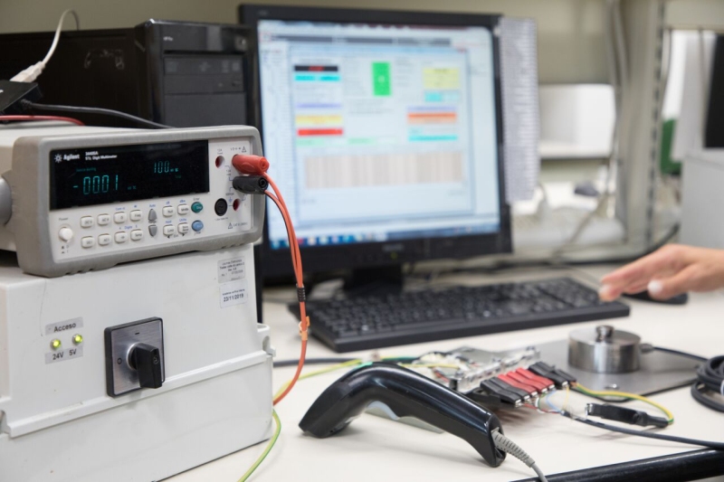
The machine checks:
- electrical insulation between the various parts of the load cell (body-shield, body-wires, shield-wires);
- correct short-circuiting of the reference wires and their power supplies;
- the input resistances between the two power supplies and the output resistances the two + and - signals;
- the no-load voltage, which is the value generated by the load cell when it is not loaded.
If the software shows that alla values are within the parameters, the test has been passed.
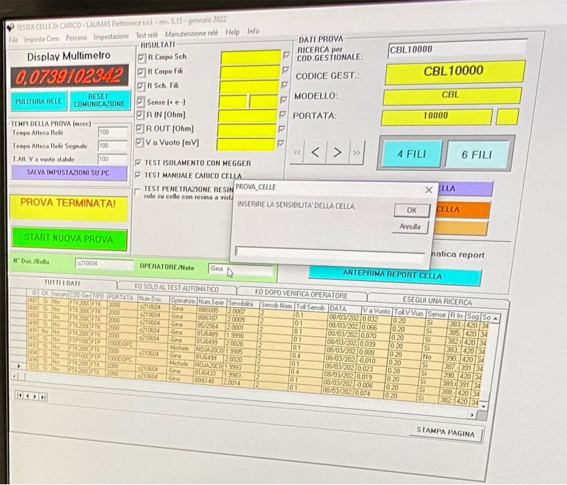
The digital multimeter measures all values in Ohms, which is a measure of resistance.
Only the no-load voltage returns a value in mV.
At the end of each test, an additional manual test is also performed. The operator applies pressure to the load cell by hand and verifies thet the multimeter value changes due to the force applied.
The test certificate is now ready to be printed out and attached to the load cell. It will include its data and the values of the verified technical characteristics.
During the manual test, the operator presses the load cell only if it is a compression cell. In the case of tension load cells, the operator instead "pulls" the sensor.
The force must always be exerted in the direction in which the load cell is to weigh.
18. Packaging and shipping
The load cell is at last ready to be packed and shipped.
The operator sends the order to the warehouse, paying particular attention that the communicated serial number is the same as the one on the load cell just tested.
The warehouse worker takes the load cell from its box and places it in a special packaging that has a locking protection system.
It is made of cardboard and a thin, high-strenght film that can be disposed of as paper and so is completely recyclable.
How does the locking system work?
On folding the two ends of the cardboard, the film stretches and completely wraps the load cell, ensuring a perfect stability with no need to add any filling material.
The load cell will not move and will be protected from any possible impact during transport.

The packing can also be reused by the recipient, thus minimizing the generation of waste at both ends of the production cycle.
The warehouse worker prepares the package, placing the load cell in its box along with the test certificate.
The surface on which he prepares the package is actually a weighing platform with many small balls that help the packaging slide onto the trolley.
Thanks to the platform, the package gets weighed already during preparation and the WLIGHT weight indicator displays and records its weight.
The warehouse worker can now seal it and affix the transport documenti identifying its contents and destination, and then ship it.

Search in the blog
Search by tag
Recent articles

Weighing solutions for weighbridges
5 different combinations using our weighing components, ideal for building both pit-mounted and above-ground industrial vehicle scales.
Read more
Weighing system for a semiautomatic big bag filling machine
Weighing system for a big bag filling machine, built for the mechanical extraction of plastic granules and their bagging into big bags up to 2 m3.
Read more
Weighing system for a hospital bed
In collaboration with Malvestio, we have developed a weighing system for a pediatric intensive care hospital bed: junction box and software for management and calibration.
Read more
Weighing and dosing system on agricultural machinery
Weighing system on a fertilizer spreader machine for controlling and dosing fertilizer, compost, etc. contained in large polyethylene hoppers. It must operate in harsh environments and integrate seamlessly with the machinery and control system.
Read moreRELATED PRODUCTS

CBL
Compression load cells