How to check if a load cell is working correctly – Test with digital multimeter
Measuring load cells resistance and voltage with a digital multimeter.
Accuracy is one of the most important characteristics of a load cell.
Accurate information is essential not only when weighing, but also in all the process management and control operations.
But what is to be done if there is a fault or malfunction on the weighing system and the load cell measurement is no longer so accurate?
There are 2 ways to check that a load cell is working properly: through built-in diagnostics offered by some instruments and through a digital multimeter test.
Built-in diagnostics
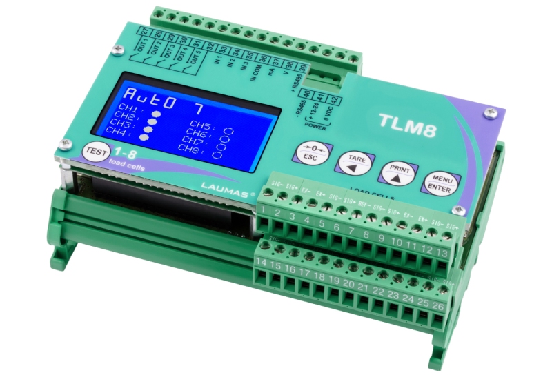
This is the on-board function of some multichannel weight transmitters and some junction boxes, such as the TLM8 and TLB4 weight transmitters, or the intelligent junction box CLM8.
If the load cell is connected to an instrument offering this possibility, the malfunction is reported directly by the weight transmitter or the junction box.
→ Read also "How to check if a load cell is working correctly - Built-in diagnostics".
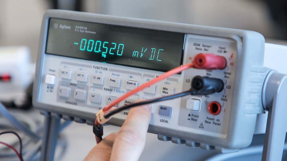
Test with digital multimeter
This is an in-depth test that is helpful when you want to measure both the resistance and the no-load voltage values of the load cell.
Here's a detailed look at how to perform the two tests.
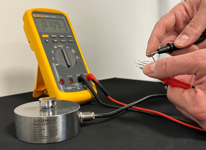
Measuring the resistance (or impedance):
1. The first thing to do is to disconnect the load cells from the instrument and check that there are no traces of moisture in the junction box due to water ingress or condensation.
If there are any, the system must be drained or, if necessary, replaced.
2. Connect the digital multimeter to the load cell you want to test.
3. Using the multimeter, check:
- The value of the resistance between the positive signal wire and the negative signal wire.
It must be the same as or similar to that indicated on the load cell data sheet (see output resistance). - The value of the resistance between the positive power supply wire and the negative power supply wire.
It must be the same as or similar to that indicated on the load cell data sheet (see input resistance). - The insulation value between the shield and any of the other load cell wires and the insulation value between any wire of the load cell and its body.
Both must be greater than the full scale of the tester.
Measuring the voltage with no load
To measure the voltage, the load cell must be tested unloaded, i.e. with no load applied.
Simply remove it from the weighing system or, if the mounting kit has one, the devices can be activated to completely unload the load cell.
This possibility is provided, for example, by the LAUMAS V10000 and VCOKDTL mounting kits.
Once the load cell has been unloaded, the following steps must be carried out:
- Make sure that there is a voltage of 5V DC +/-3% on the power supply wires of the load cell connected to the indicator or weight transmitter.
- Connect the load cell positive and negative signal wires directly to the tester.
- Measure the response signal between the two wires with the multimeter set to the mV scale
It must be between 0 and +/- 0.5 mV (millivolts). - Exert a force on the load cell while respecting the direction of load and check that there is a signal increment in mV (millivolts).


