How to check if a load cell is working correctly - Built-in diagnostics
Everything that can be monitored with single-channel and multichannel instruments.

As already presented in the guide “How to check if a load cell is working correctly – test with digital multimeter”, accuracy is one of the most important characteristics of a load cell.
Malfunctioning and faults can occur within a weighing system, so having the chance to promptly locate the issue is fundamental.
To check that everything is working properly, we can take advantage of the various diagnostic features on LAUMAS weight transmitters and indicators connected to load cells.
What can be monitored through the diagnostic function, either by the instruments or remotely via PLC?
First of all it is necessary to distinguish between the features in the single-channel and multichannel instruments.
Single-channel instrument built-in diagnostics
Single-channel instruments are structured so that the converter inside reads just one input channel; the measured data therefore refer to a single sensor.
By connecting the load cell to the single-channel instrument, the latter is able to correctly detect faults on the connection between the single load cell and the instrument.
In the case of multiple load cells connected in parallel to the single-channel instrument, the diagnostic function will lose precision: the single-channel instrument is in fact able to detect malfunctioning of the weighing system, but not to signal which specific load cell has the fault.
It is also possible that, due to the parallel connections to a single reading channel, the instrument might not signal some faults.
On single-channel instruments, in the “TEST” menu item, you can also see the value of the voltage in real time, that is the measurement in mV of the signal that the instrument identifies in input while it is in operation.
This is very useful in order to measure abnormal values that could mean that the load cell is not working properly.
Multichannel instrument built-in diagnostics
Multichannel instruments (such as the weight transmitters TLM8 and TLB4 and the intelligent junction box CLM8) have an analog-digital converter that enables obtaining a digital value for each of the input channels.
Here, too, there is a function that enables viewing the measurement of the signal in mV in real time, that is the value of the voltage, but unlike the single-channel instruments, it is shown for each single load cell.
Being able to connect multiple load cells to the multichannel instrument, each one to its specific input, there are additional diagnostic features available that are more accurate than those of the single-channel instruments.
These advanced diagnostics functions facilitate the operations of checking and managing the process, in fact they permit:
Monitoring the state of the connection for each single channel and detecting malfunctioning, errors and faults
First of all it is necessary to connect the load cells to the multichannel weight transmitter or to the intelligent junction box CLM8 and start the instrument.
Since it is possible to read what is happenaing on each single channel, when switching on it is possible to monitor the signals on the various input channels.
This type of monitoring, which permits detecting malfunctioning, faults and errors on the single channels and identifying the load cell with the problem, can be activated in 2 ways:
1 - Automatic search.
When this function is active, each time the instrument is switched on it automatically scans each single channel and identifies which channels each load cell is actually connected to, using only the active ones to calculate the weight.
2 - Manual channel selection and saving the configuration.
With this function the user tells the instrument which channels are actually operative and can save the configuration to make it permanent.
In this way, each time the instrument is switched on ot detects whether the selected channels are actually still operative and signals an error if a load cell is no longer connected.

Display indicating 6 active channels. Channel 7 and 8 are off/ disabled.
What is the advantage of saving the configuration of the channels?
Should a load cell break while the system is off, at the next start-up the instrument will send an error message signaling on which channel there is the fault.
This does not happen with automatic detection. Should a fault occur while the instrument is not in operation, it would not be signaled at the next switch-on.
In fact, the instrument discards channels that are not operative at the time of start-up, considering them as "missing load cells".
How is manual channel selection activated?
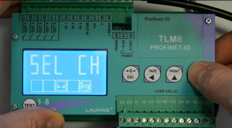
In the "CALIB" menu, select "SEL CH" and press ENTER.
The transmitter display will show the actual number of connected load cells.
If the number matches, press ENTER again to save your selection and make it permanent.
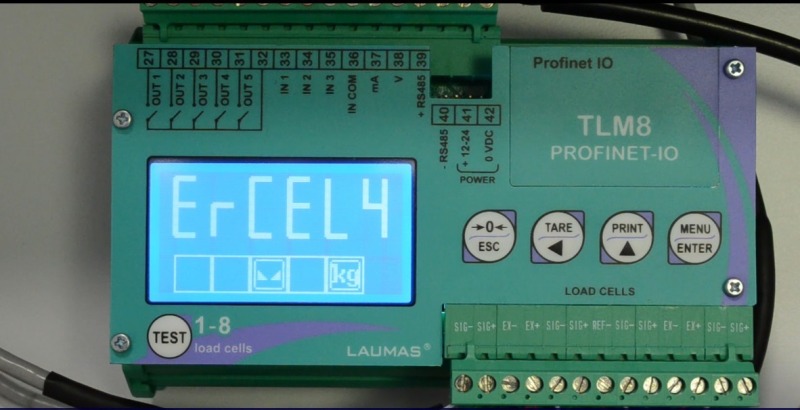
Once the setting has been saved, should an error occur on one of the connected load cells, the display will show ERCEL followed by a number identifying the exact position of the damaged load cell.
Measuring and monitoring the weight distribution on the calibration zero and on values other than zero
These functions are in the "TEST" menu under the specific item "DIAG".
Thanks to this function the user can at any time view and check how the weight on the scale is being distributed on the various load cells and how this distribution changes by modifying the weight or the position of the objects.

Weight distribution in percentage on active channels
By using this information it is possible to detect some abnormal conditions both when monitoring zero and when monitoring values other than zero.
MONITORING THE WEIGHT DISTRIBUTION ON THE CALIBRATION ZERO
The system saves how the weight is distributed on the various load cells when the scale is on zero, that is when the system is unloaded.
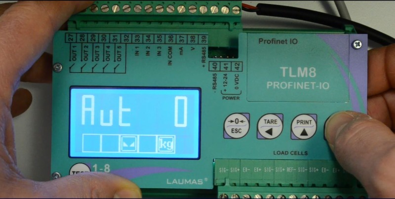
After unloading the scale, it is possible to enable zero diagnostics: in the DIAG menu simply set AUT 0 onto YES and press ENTER.
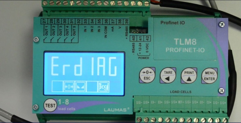
During system operation, if the weight distribution at zero deviates from the saved value, the instrument will show the error message ERDIAG.
MONITORING THE WEIGHT DISTRIBUTION FOR VALUES OTHER THAN ZERO
It is possible to set the same type of alarm also for load values other than zero. This function is called "load diagnostics".
It is useful in order to identify mechanical problems in systems where the distribution of the load inside the container is always the same, as for example happens with liquids.
Normally, liquids occupy all the space inside their container (e.g. a silo) and the distribution is always the same on each load cell.
Thanks to the load diagnstics function it is possible to divide the entire full scale into intervals of measurement and save each single load distribution.
Once all the distributions have been saved, when the measured weight comes within one ot these intervals, the system will compare the distribution of the load on the load cells so as to signal any errors.
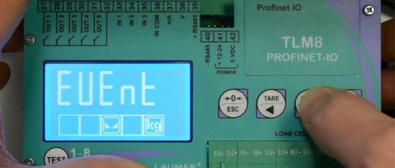
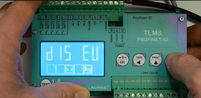
Recording events
The last 50 events recorded by the system are saved under DIS EV int he EVENT menu.
Recording events provides data and additional information concerning: errors on the weight, calibrations made and equalizations performed.
It is very useful above all for technical support providers.
In the event of an error occurring and it not being possible to identify its origin, this information can be used to quickly locate and resolve the issue.
To see how to apply the specific procedures
Search in the blog
Search by tag
Recent articles

Weighing solutions for weighbridges
5 different combinations using our weighing components, ideal for building both pit-mounted and above-ground industrial vehicle scales.
Read more
Weighing system for a big bag filling machine
Weighing system for a big bag filling machine, built for the mechanical extraction of plastic granules and their bagging into big bags.
Read more
Weighing system for a hospital bed
In collaboration with Malvestio, we have developed a weighing system for a pediatric intensive care hospital bed: junction box and software for management and calibration.
Read more
Weighing and dosing system on agricultural machinery
Weighing system on a fertilizer spreader machine for controlling and dosing fertilizer, compost, etc. contained in large polyethylene hoppers. It must opearate in harsh environments and integrate seamlessly with the machinery and control system.
Read more
")
 8 CHANNELS FOR LOAD CELLS")