Weighing systems and load limiters for bridge cranes
4 different solutions to apply to new or existing systems.

Requirement
Make a bridge crane with a weighing and load limiting system for the lifting sector.
The bridge crane has a capacity of 20 metric tons, with a lifting hook with 4 sections of rope of diameter 18mm.
Our solutions
We have created 4 versatile designs that fit the customer's different goals.
They are all intended for using the multichannel weight transmitter TLM8, while the types of load cells offered vary.
1. Solution with shear beam load cells
For highly accurate weighing systems that can be compared to an industrial balance in terms of precision, repeatability and lack of friction. Ideal solution for bridge cranes of new construction.
2. Solution with tension load cells
For precise weighing systems with minimal impact on the existing structure.
3. Solution with pin load cells
For weighing and load limitation, for new or existing bridge cranes.
4. Solution with wire rope load cells
For load limitation only, without any modification to the existing bridge crane.
1. Solution with shear beam load cells.
Ultra-accurate weighing for new constructions
The system consists of:
- 4 shear beam load cells FTP 10000 kg
- 4 ball joints EM-DADO (EM25DADO) with M24 thread
- 4 threaded rods
- 1 TLM8 weight transmitter in an IP67 box made of polycarbonate; with functional safety manual
- 1 remote display RIP6100IP65 with 6 digits and 95 mm high.
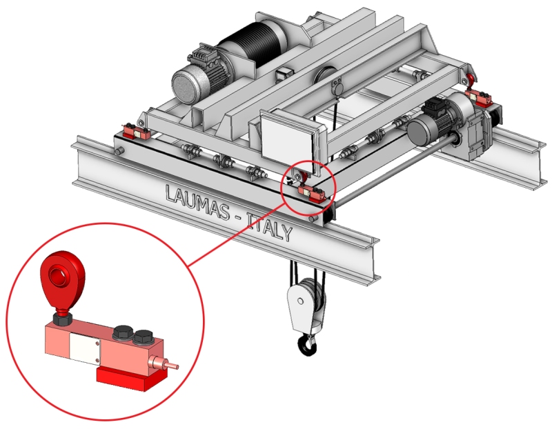
The overall full scale of the system is 40000 kg, exactly twice its capacity.
Since overhead weighing systems require a greater safety margin than traditional weighing systems, we advise oversizing the capacity of the load cells to have them work at 40/50% of their capacity.
How to choose the right load cell for an overhead weighing system?
When selecting the load cell it is important to consider that the breaking load must be at least 5 times the rated capacity of the bridge crane.
The safety ratio between the two must therefore be at least 5 to 1.
It is assumed that this solution is applied on a new bridge crane, in which the construction of a counterframe is envisaged, allowing both the frame to be supported and the load cells to be placed between the counterframe and the weighed structure (consisting of a frame and a lifting winch).
How does it work?
- The 4 load cells with a ball joint are positioned at the top of the counterframe and support the weighed frame on which there is the lifting winch.
- The threaded horizontal rods are inserted in the middle of the 4 sides of the weighed structure and secured to the weighed frame, in the middle, while at the 2 ends they are fastened to the counterframe.
- The weight transmitter in the box is located directly on the frame, outside the power panel, and connected to the 4 load cells.
- The remote display is fastened on the frame and connected to the weight transmitter via an RS485 port.
The added value
- The threaded rods act as a system to counter the lateral forces, absorbing them completely.
The load cells thus sense only the orthogonal force, i.e., the downward force. - The TLM8 weight transmitter, installed directly on the frame, replaces the junction box and performs its task.
- The 5 relay outputs of TLM8 act as a load limiter: they can be programmed as safety thresholds to stop the operation of the bridge crane in the event of system overload. By setting the total capacity of the bridge crane (in this case 20000kg) as the threshold, the bridge crane will lock if the raised load exceeds the threshold.
- The large-digit remote display helps the operator have direct feedback of the weight that is being lifted while maneuvering the bridge crane with the remote control.
Is this solution also valid for existing bridge cranes?
Making mechanical changes to an existing system is possible, even if it is especially invasive. For this specific case, we therefore recommend designing a new system.
The design phase is essential in order to be able to plan for the counterframe that will accommodate the weighed frame with a lifting winch
2. Solution with tension load cells.
Precise weighing for new or existing bridge cranes.
The system consists of:
- 1 tension load cell CTL 10000 kg
- 2 ball joints EM-DADO (EM30DADO) with M30 thread
- 1 TLM8 weight transmitter in an IP67 box made of polycarbonate; with functional safety manual
- 1 remote display RIP6100IP65 with 6 digits and 95 mm high.
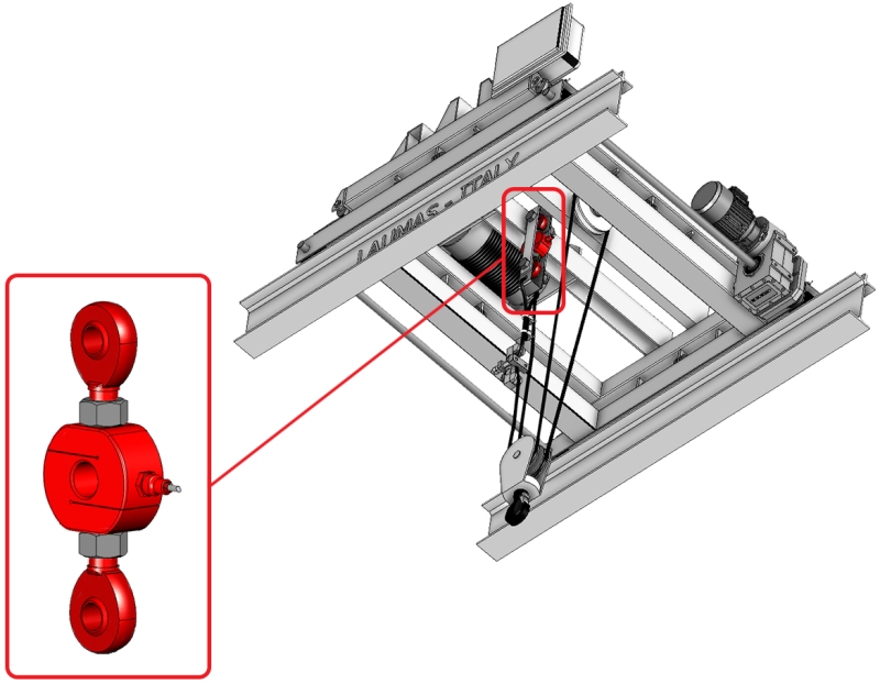
How does it work?
- The load cell with a double ball joint is incorporated in the system in such a way that one joint is anchored to the rope anchorage and the other is coupled to the rope.
- The weight transmitter in the box is connected to the load cell and inserted in the power panel installed directly on the frame.
- The remote display is fastened on the frame and connected to the weight transmitter via an RS485 port.
The added value
- The load cell is very easy to install on existing bridge cranes.
With a simple modification of the rope already on the structure, good system accuracy can be achieved. - The joints applied to the load cell enable it to be oriented and receive the force at right angles even when the angle of the rope changes in relation to the structure.
This ensures that the load cell does not make any weighing errors and ensures good accuracy and repeatability.
How to choose the correct capacity of the load cell?
To choose the correct load cell capacity, the total capacity of the system (20000 kg) has to be divided by the number of rope sections (4), since only ¼ of the lifted load remains on the fixed end where the load cell is located.
In order to maintain a safety margin at all times, we suggest then doubling the result: 20000 / 4= 5000 kg x 2= 10000 kg.
The suggested capacity for the load cell will then be 10000kg.
3. Solution with pin load cells.
Weighing and load limiting for new or existing bridge cranes
The system consists of:
- 1 pin load cell LAU 5000 kg
- 1 TLM8 weight transmitter in an IP67 box made of polycarbonate; with functional safety manual
- 1 remote display RIP6100IP65 with 6 digits and 95 mm high.
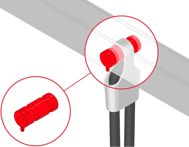
How does it work?
- The load cell is positioned in place of the existing pin on the anchorage where the steel rope originates.
- The weight transmitter in the box is connected to the load cell and inserted in the power panel installed directly on the frame.
- The remote display is fastened on the frame and connected to the weight transmitter via an RS485 port.
The added value
- It is easy to install on existing bridge cranes.
Simply replace the mechanical pin that acts as a rope anchorage with an equivalent measuring pin, that is, a pin load cell, which is perfectly interchangeable from a mechanical point of view. - Pin load cells are particularly compact and safe and have a high safety coefficient.
- This solution makes it possible to combine a load limiter and a weighing system together with reasonable precision.
- It's adaptable to any need. In addition to the standard LAU load cell, it is possible to design and build a custom pin load cell, based on the design provided by the customer (Custom load cells).
What does pin load cells have a high safety coefficient mean?
The safety coefficient is a design value that makes the load cell stiffer and more robust, making it particularly suitable for lifting systems.
Pin load cells are therefore designed to have much less deformation than standard load cells, with the same load applied.
4. Solution with wire rope load cells.
Load limiter for existing bridge cranes
The system consists of:
- 1 load cell for wire rope measuring FUN, with maximum tension on the rope 10000 kg
- 1 TLM8 weight transmitter in an IP67 box made of polycarbonate; with functional safety manual
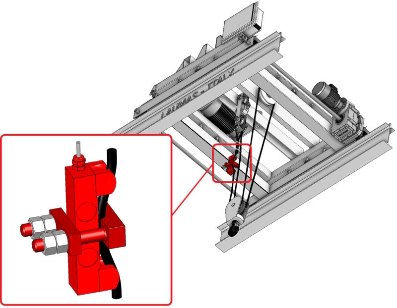
The 10000 kg FUN load cell can be installed on ropes with a diameter of between 16 and 26mm, so it is perfect for the one of our system (18mm).
In this case you have 4 rope sections, so you will need to divide the maximum capacity of the bridge crane by the number of sections (20000 kg/4). Because of the number of sections, 5000 kg will then be weighing on the load cell.
This allows the system to work safely at 50% capacity.
How does it work?
- The load cell is simply inserted as a terminal at the start of the rope anchored to the rope anchorage.
- The TLM8 weight transmitter in the box is connected to the load cell and inserted in the power panel, which is installed directly on the frame.
The added value
- No changes are made to the system
- Installation is simple, fast and non-intrusive
- The load limiter function is carried out by the 5 relay outputs on the TLM8.
Simply set the total capacity of the bridge crane as a safety threshold and the bridge crane will lock if the weight value of the lifted load exceeds the set threshold.

